A Programmable Logic Controller, or PLC, is a special computer devices to control system that continuously monitors input and generate output based upon a custom program. For simplification, PLC is like our laptop or personal computer but only to run special program in controlling other devices during its lifetime. It has high reliability and stable in rough condition, so many manufacturing line prefer to use it than computer.
Simple example about utility of PLC is to leverage function of a switch that turn on/off a light. If we push the switch button the light would turn on or off immediately. But how if we need to make the light on 30 second after switch pushed? It will be hard if we use mechanical clock and bunch it mechanically with the switch. PLC will save our day. We just need to wire switch, PLC, and lamp in a diagram. Then we need to tell the PLC (program) to turn on the lamp 30 second after we push the switch. That’s how PLC be used in simple way.
This article will guide you how to install and program PLC in simulator. It’s too expensive for us to buy real PLC just for learning. Thanks for software engineer that build simulator of PLC so we can learn it without contact directly with the real one. This tutorial will use LogixPro 500 as main software.
Step 1:Download RSLogix Simulator
Download RSLogix Simulator installer for free in 15 days trial.Step 2: Install RSLogix Simulator
Install RSLogix Simulator by right click and select “Run as Admin”. Then follow the instruction of installation step by step.Step 3: Run Program
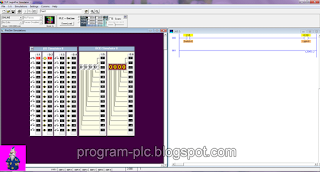
Go to your desktop and double click shortcut of LogixPro. Your program will start immediately and you will see window like this. Insert your user key if you have one, otherwise use the limited trial version.Step 4: Open Simulator
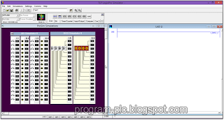
Select from main menu Simulations and click I/O Simulator. It will open ProSim Simulation window beside the program window. You can maximize it to show clearly. Hover your mouse to switch symbols, it will turn your mouse cursor as a hand icon. You can click this switch to simulate turn on/off and see how the light turns. You can also change the switch type by right click on switch. This simulator window consist of 32 switches and lights. Two group of 16 switches connected to 2 input cards of our PLC simulator. And two groups of lights are connected to 2 output cards of our PLC. Input card addressed as I:1 and I:3 while output cards are addressed O:2 and O:4.Step 5: Build First Program
To build a program you will have to input any wiring at ladder window. We will make a simple switch program from input I:1/0 that will turn O:2/0 state as the output. To do it you have to add New Rung from the toolbar. Then click Examine If Closed
  followed by Output Energize
 .
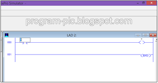
.Your three action before will generate this diagram on the ladder. Double click on the question mark (?) and fill the value in left side with I:1/0 and O:2/0 at the right side. This action will set the input refference in wire 000 to switch I:1/0 and set the output to light O:2/0.
You can also edit symbols info by right click with your mouse above the symbol. Then click Edit Symbols. Write Switch-0 for the input and Light-0 for the output. Your program then will looks like this.
Step 6:Download Program to Simulator
After your ladder program finished, it is time fot our PLC simulator to download our ladder program. To do this you have to show your PLC Control Panel. You can show it by toogle your toolbar. Then you need to download the program to PLC by clicking Download button.Step 7: Run Simulator
After your PLC success downloading your program, now it is time to run your simulator. Simply click radio button beside RUN label. Now your virtual PLC is running. You can simulate your input by clicking switch I:1/0. Try it and see how your light O:2/0 turn it’s state. You can also change your switch type during simulation process by right click above your switch. Just try and let your creativity take action.To stop simulation process you just need to click PGM radio button. Then to edit your program you need toogle your toolbar first. Edit your program simply by drag and drop the symbols or delete it. After finish editing, do not forget to download first your program before running simulation again. If you forget to download after some modification, then your PLC will run your last download program.
Video about Start Learning LogixPro 500 PLC Simulator:
Labels:
PLC Simulator
PLC Simulator


